Solutions for compensation of reactive power
Automatic Power factor correction unit is fully automatic in operation and can achieve desired power factor under fluctuating load conditions.
Components:
- Capacitor banks
- Contactors for capacitor switching
- Power factor controllers
- Detuned filter reactors
SYSTEMS AND TYPES OF COMPENSATION
When selecting a capacitor bank, there are two compensation systems.
Fixed type capacitor banks
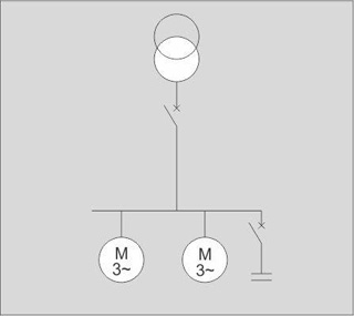
- The reactive power supplied by the capacitor bank is constant irrespective of any variations in the power factor and the load of the receivers, thus of the reactive energy consumption of the installation.
- These capacitor banks are switched on:
- Either manually by a circuit breaker or switch
- Or semi-automatically by a remote-controlled contactor
- This type of capacitor bank is generally used in the following situations:
- Electrical installations with constant load operating 24 hours a day
- Reactive compensation of transformers
- Individual compensation of motors
- Installation of a capacitor bank whose power is less than or equal to 15% of the power of the transformer
Automatic type capacitor banks
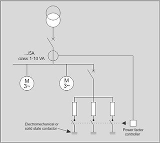
- The reactive power supplied by the capacitor bank can be adjusted according to variations in the power factor and the load of the receivers, thus of the reactive energy consumption of the installation.
- These capacitor banks are made up of a combination of capacitor steps (step = capacitor + contactor) connected in parallel. Switching on and off of all or part of the capacitor bank is controlled by an integrated power factor controller.
- These capacitor banks are also used in the following situations:
- Variable load electrical installations
- Compensation of main LV distribution boards or major outgoing lines.
- Installation of a capacitor bank whose power is less than or equal to 15% of the power of the transformer
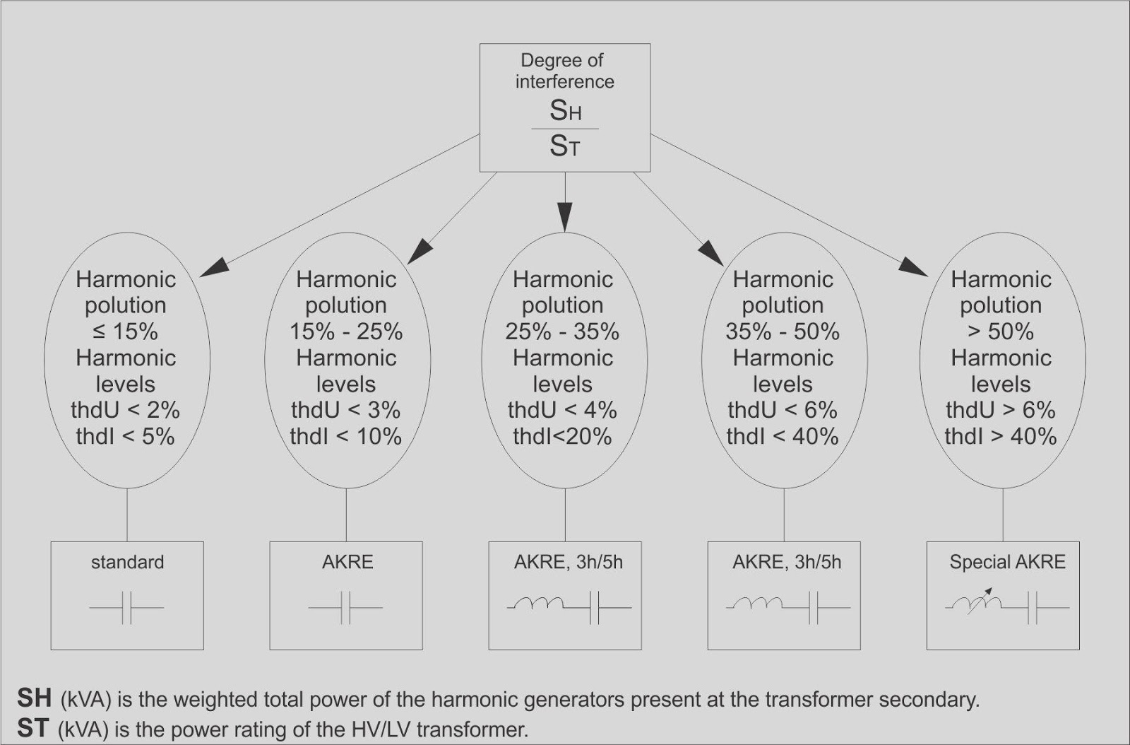
PROTECTING CAPACITORS FROM HARMONICS
By design and in accordance with current standards, capacitors are capable of continuously withstanding an rms current equal to 1.3 times the nominal current defined at the nominal voltage and frequency values.
This overcurrent coefficient has been determined to take account of the combined effects of the presence of harmonics and overvoltage (the capacitance variation parameter being negligible).
It can be seen that depending on the degree of harmonic pollution SH (power of the harmonic generators), this coefficient is generally insufficient and that the parameter Ssc (short-circuit power), directly related to the power of the source ST, is preponderant in the value of the parallel resonance frequency (Fr.p).
By combining these two parameters, SH and ST, three types of main supply can be defined, with a corresponding “type” of capacitor to be installed: